November 15, 2018
Eric Rice
Motors serve as integral components of motion control systems for industrial conveyors. Typically, conveyor applications operate at either a constant or variable speed, requiring only velocity control from a main drive motor. Positioning conveyors, such as those used for automated checkweighers, require more precision control. In these applications, the main drive must start and stop the positioning conveyor with moderate to high precision.
While DC and AC motors are popularly used to maintain velocity control for fixed or constant speed conveyor applications, step and servo motors offer more precise positioning capabilities for conveyors requiring more exact precision movement. Steppers are often the motor of choice, while servo motors offer numerous benefits for more demanding moves.
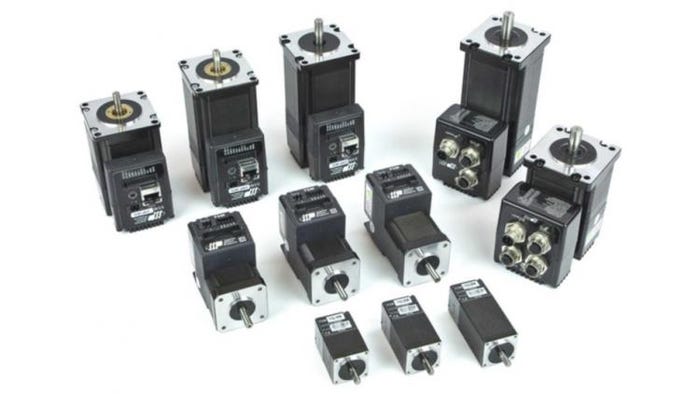
Stepper motors normally operate in open-loop control and offer the advantages of simplicity, excellent positioning and economy. But when configured with a feedback mechanism—such as an integrated high-resolution encoder—closed-loop stepper motors provide velocity and position information back to the drive/controller. The high torque, fast dynamic response of closed-loop systems addresses the demands of high-performance positioning conveyors.
Speed, torque, accuracy and size are important parameters to consider when choosing the right motor for a conveyor application. Motor suppliers can provide the expertise and tools to assist you in selecting the right design for your application.
After specifying the correct motor, choosing a proper motor control method comes next. Here are three of the most popular methods for controlling both step and servo motors used in positioning conveyors.
1. Pulse Control
Digital Pulse Control, also known as step and direction control, is a common method for controlling any step or servo motor. Digital pulse control is a good option if the primary PLC or controller in the machine contains one or more high frequency outputs, such as 20 kilohertz (kHz) or greater.
A minimum pulse output frequency of 20 kHz is required for step and direction control. While many users may want to use 100 kHz or more (many controllers offer frequencies as high as 2 or 3 megahertz or MHz), these high-frequency outputs add to system costs. Use lower frequency outputs by implementing a stepper drive or integrated stepper motor with Microstep Emulation. This powerful advancement in step motor technology enables smooth, microstep operation even when motors use low frequency pulse outputs.
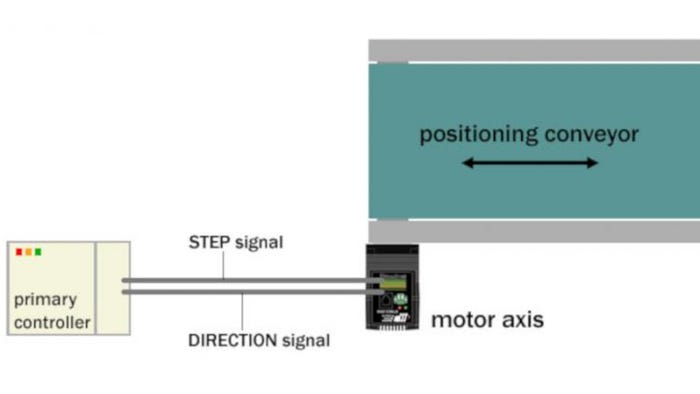
Figure 1: This pulse control diagram shows how the primary controller outputs STEP and DIRECTION signals to the motor axis.
The configuration of this control scheme (see Figure 1 above) includes connecting the pulse output from the PLC to the step input of the motor drive or integrated motor. A second, non-pulse output is tied to the direction input. The number and frequency of pulses transmitted to the step input determine the travel length and speed of the conveyor, respectively. The signal (high or low) at the direction input determines the travel direction—forward or reverse. For smooth conveyor starting and stopping, the PLC/controller must ramp the frequency of pulses up and down to create smooth accelerations and decelerations. Without this capability, the conveyor will jerk when starting and stopping.
2. Velocity Control with Analog Input
Using a variation of discrete input/output (I/O) signals with one or two digital inputs plus an analog input is another popular scheme for controlling step and servo motors with positioning conveyors.
In this configuration, Run/Stop is the first digital input. When Run/Stop is set, the motor automatically reaches and runs at target velocity. When the Run/Stop input is reset, the motor decelerates to a stop. As motor acceleration and deceleration are configured in software during axis commissioning, the axis automatically controls them. A second digital input can control direction (forward/reverse).
While the target velocity of the motor is configurable in software to a fixed value, many users elect to control the speed with an analog signal (see Figure 2 below).
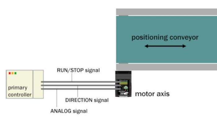
Figure 2: This velocity control diagram shows how the primary controller provides RUN/STOP and DIRECTION digital signals, as well as an ANALOG signal for velocity reference to the motor axis.
This option provides much more flexibility to the machine designer. By configuring the motor axis to ratio its target velocity according to the voltage level at the motor axis’ analog input, the machine designer can accurately control the target velocity of the conveyor for different process conditions. Some conditions may require that the conveyor run faster than others. Many drives and integrated motors have at least one analog input that accepts 0 to 5 volts or up to +/- 10 volts. Analog velocity control is an effective method for controlling both the position and speed of the conveyor using a minimal number of I/O points. This control scheme is easy to program in the primary controller.
3. Network Control (Distributed Control)
Network control offers the greatest flexibility to the user, especially for those preferring to offload some of the control functions. Network control (see Figure 3 below) involves a permanent serial or fieldbus connection between the primary controller and the motor drive or integrated motor. This connection replaces all or most of the discrete I/O signals used in the previous two methods.
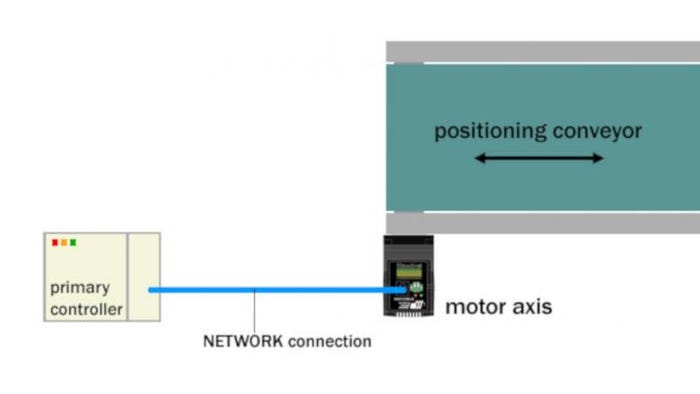
Figure 3: This network control diagram shows the network connection between the primary controller and the motor axis. The network connection can be a serial interface such as RS-232, RS-485 or Ethernet, or an industry-standard protocol such as EtherNet/IP, Modbus or CANopen.
Many drives and integrated motors on the market today support network interfaces for RS-232, RS-485, Ethernet TCP and Ethernet UDP, as well as EtherNet/IP, Modbus and CANopen. Any of these serial interfaces work for single-axis applications where the primary controller must control only one axis. However, RS-232 does not work for multi-axis applications when controlling more than one axis.
Once a network connection is made, all commands from the primary controller to the motor axis are sent over the network connection. The exact details of the commands vary by the connection method. For discussion purposes, this article will focus on sending SCL (Si Command Language) commands over an RS-232 or RS-485 connection.
Simple and easy-to-use, SCL commands are defined with two letters and follow a simple syntax easily adopted by programmers. The syntax for streaming an SCL command over an RS-232 or RS-485 connection can be shown as:
FL20000
In this example, the command is FL, which stands for Feed To Length and represents an incremental or relative move command. The number 20000 is the distance parameter for this command and indicates 20,000 increments of motion. For a step motor, each increment is one step, while for servo motor, each increment is one encoder count. The at the end of the string symbolizes a carriage return (ASCII 13), which designates the end of the command string. Upon receipt of this command string, the motor axis indexes the conveyor forward a distance of 20,000 increments.
The SCL command set contains additional commands for velocity, acceleration and deceleration, as well as for movement in both forward (positive) and reverse (negative) directions. More than 100 commands are available in SCL, including those for absolute moves, homing moves and registration moves. For a dictionary of SCL commands, refer to Host Command Reference.
To choose which of the control schemes is right for your positioning conveyor application, consider the requirements for position and velocity, as well as the type and existing capabilities of the primary controller or PLC already in your machine. Adding a step-and-direction control module to your PLC or controller is easy. If the function already exists and is available, the pulse control method is a good choice. Pulse control provides accurate positioning.
If simple run/stop and direction control is only needed, consider the analog control scheme. As explained, this scheme is upgradeable any time with an analog signal for varying the conveyor speed. Keep in mind that the accuracy for the velocity control scheme to position the conveyor (starting and stopping) is based on the timing of setting and resetting the run/stop input.
Finally, if your PLC or controller has an available network connection, network control provides highly accurate positioning, as well as the opportunity to query the motor axis for status. Having the capability to query the motor axis for information—such as motor fault and alarm status—can be beneficial to maintaining the reliability of machine operation.
An application engineer, Eric Rice is marketing director at Applied Motion Products. Founded in 1978, the company specializes in high-precision, cost-effective motion control products. Reach Rice at [email protected].
You May Also Like


