March 11, 2015

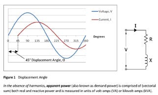
Displacement angle.jpg
Companies continue to explore ways to reduce costs - and one area that is drawing interest is power factor correction. But the question of whether improving power factor will translate directly to the bottom line is not easily answered. It requires a better understanding of power factor in general, as well as harmonics, a facilities electrical distribution system - and the billing practices of the electrical utility or energy provider. In addition to potentially saving money, there are other additional benefits to power factor correction - such as reduced carbon footprint.
What is Power Factor - and Why is it Important to My Bottom Line?
Electrical power in an AC circuit is comprised of three components: real power (P), reactive power (Q) and apparent power (S).
Real power is the work producing power measured in watts (W), or kilowatts (kW). Real power produces the mechanical output of a motor - in a packaging environment this might include the motors which power a form-fill-seal machine, for example, or power the conveyor which moves materials through the plant.
Reactive power, on the other hand, does not do any work but is nonetheless needed to operate equipment. It is measured in voltamperes- reactive (VAR) or kilovar (kVAR). There are many examples of inductive loads found within packaging facilities - including motors, transformers, fluorescent lighting ballasts, and power electronics. There are two components to current drawn by an inductive load - magnetizing current and power-producing current. The magnetizing current is required to sustain the electro-magnetic field in a device and creates reactive power. An inductive load draws current that lags the voltage, in that the current follows the voltage wave form. The amount of lag is the electrical displacement (or phase) angle between the voltage and current (see Figure 1).
In the absence of harmonics, apparent power (or demand power) is comprised of (vectorial sum) both real and reactive power and is measured in units of volt-amps (VA) or kilovolt-amps (kVA). (See figure 2 showing power triangle).
Power factor (PF) is a measure of how effectively electrical power is being used. It is the ratio of the real power to apparent power and represents how much real power electrical equipment utilizes. Power factor is also equal to the cosine of the phase angle between the voltage and current waveforms.
Electrical loads demand more power than they consume. Induction motors convert at most 80 - 90% of the delivered power into useful work or electrical losses. The remaining power is used to establish an electromagnetic field in the motor. This field is alternately expanding and collapsing (once each cycle) so the power drawn into the field in one instant is returned to the electric supply system in the next. Therefore, the average power drawn by the field is zero and reactive power does not register on a kilowatt-Hour meter. The magnetizing current creates reactive power. Although it does no useful work it circulates between the generator and the load - placing a heavier drain on the power source as well as the transmission and distribution system.
Stated another way, when a utility serves a facility that has poor power factor, the utility must be capable of supplying higher current levels to serve a given load (see figure 3). From the customer's viewpoint, the current carrying components of their power system (generators, transformers, cables, circuit breakers and fuses for example) must also be able to carry this higher total current. (See figure 3)
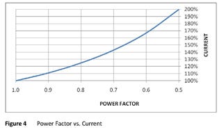
Since utilities are paid on the basis of energy consumed (kWh) and the reactive component of current does not register on a kilowatt-hour meter, many utilities impose a power factor penalty or peak demand (kVA) billing element to receive income for the total power they are required to deliver to a given customer. As the power factor drops the system becomes less efficient (see figure 4). For example, let's assume that two plants have the same real power 
power factor vs. current.jpg
demand - but one plant has a power factor of 0.85 while the other has a power factor of just 0.70. In this instance, the utility must provide 21% more current to the second plant to meet the demand. Without a power factor billing element, the utility would receive no more income from the second plant than from the first. (see figure 4).That is why many utilities establish a power factor penalty in their rate schedule. Often a minimum power factor, of 0.85 to 0.95, is established. When a customer's power factor drops below the minimum value, the utility collects a low power factor revenue premium on their bill. Typically the lower the power factor, the higher the premium.
Another way some utilities collect a low power factor premium is to charge for kVA (apparent power) rather than kW (real power).
Other utilities provide customers with a credit for high power factor. Generally, utilities impose power factor penalties or apply credits only on their larger commercial and industrial customers. With a diverse range of billing rate structures imposed by electrical utilities, it is imperative to fully understand the billing method employed.
Improving Power Factor
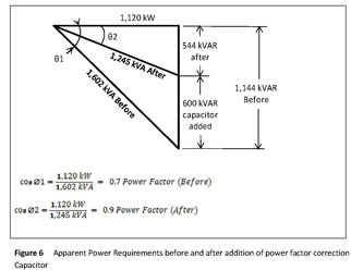
The most economical way to improve a facility's power factor is by adding capacitors. Recall that the current through an inductive load lags the voltage, but current to a capacitor leads the voltage. Thus capacitors serve as a leading reactive current generator to counter the lagging reactive current in a system. Simply stated, capacitors supply the magnetizing current required by motors at or near the motor site, instead of from the utility (see figure 5). This frees up utility capacity to provide more real power. Determining the cost-effectiveness of power factor correction - and the equipment payback - depends on a utility's power factor penalties. It is crucial to understand the utility's rate structure to determine the return on investment to improve power factor. (see figure 6)
Maintaining a high power factor in a facility will yield direct savings. In addition to reducing power factor penalties imposed by some utilities, there may be other economic factors that, when considered in whole, may lead to the addition of power factor correction capacitors that provide a justifiable return on investment. Other savings such as decreased distribution losses, improved voltage reduction, and increased facility current carrying capacity are less obvious but nonetheless real. In addition there are other indirect benefits such as a result of more efficient equipment performance or reduced carbon emissions, to consider.
As power factor of the system is improved, the total current flow will be reduced - which permits additional loads to be added and served by the existing system. In the event that equipment, such as transformers, cables, and generators, may be thermally overloaded, improving power factor may be the most economical way to reduce current and eliminate the overload condition.
Including power factor correction capacitors in new construction or facility expansions can theoretically reduce project costs through decreasing the sizes of transformers, cables, buses and switches. In practice, however, ampacity ratings are a function of full-load equipment values and size reductions may be precluded by electrical codes.
Distribution Losses & Voltage Improvements
Distribution losses in a facility can be reduced by the addition of capacitors and the resulting increase in power factor. Since distribution losses are small to begin with, capturing a major portion of them provides a minimal overall yield on the system. Although the economic benefit from distribution losses alone may not be sufficient to justify the installation of capacitors, it is an additional benefit, especially in facilities with many transformers and long feeders that serve low power factor loads.
Capacitors will also raise a circuit's voltage; however like reduction of distribution losses, it is rarely economical to apply them in industrial plants for that reason alone.
A Quick Note on Harmonics
We've made the assumption that a facility does not have significant harmonic currents present - to simplify the discussion of power factor correction, but a cautionary word is required. There are many harmonic inducing products commonly used in manufacturing - including variable frequency drives, soft starters for motors, uninterruptible power supplies and even PCs - and their presence can make power factor correction more complicated. Although capacitors themselves do not generate harmonics, when capacitors are applied to circuits with non-linear loads that interject harmonic currents, problems can arise. Those capacitors may lower the resonant frequency of that circuit 
power requirement.jpg
enough to create a resonant condition. Resonance is a special condition in which the inductive reactance is equal to the capacitive reactance. As resonance is approached, the magnitude of harmonic current in the system and capacitor becomes much larger than the harmonic current generated by the nonlinear load. The current may be high enough to blow capacitor fuses, create other "nuisance" problems or develop into a catastrophic event. A solution to this problem is to detune the circuit by changing the point where the capacitors are connected to the circuit, changing the amount of applied capacitance or by installing filter reactors to a capacitor bank which obviously increases its cost.If a facility has more than 15% non-linear load, a harmonic study should be performed before applying capacitors. The presence of harmonics can affect the proper operation of machinery, equipment, and processes, which can have an economic impact. The results of problematic harmonics need to be considered when evaluating operating costs.
Capacitor bank considerations and associated costs
The type of capacitor banks selected and their location within the circuit have an impact on the cost. Deciding where the capacitance should be located, however, is more difficult than determining the total capacitance required. Such questions as whether a single large capacitor is preferable to small capacitors are individual loads, or whether fixed or automatically switched capacitors be used, are worth considering based on individual circumstances.
Since capacitors act as a kVAR generator, the most efficient place to install them is usually directly at an inductive load for which the power factor is being improved. The value of individual motor reactive load is cumulative toward the overall plant reactive power. Therefore, when you improve the power factor of a single motor, you are reducing the plant's overall reactive requirement. If a plant has many large motors (25 hp or more), it is usually economical to install one capacitor per motor and switch the capacitor and motor together. Also, the closer the capacitor is located to the inductive load, the greater the improvement in distribution losses.
However, adding fewer, large capacitor banks is generally less expensive than smaller banks due to a reduced per kVAR costs due to reduced installation costs. This is primarily a result of decreased installation costs. If a plant contains many small motors (1/2 to 10 hp), it may be more economical to group motors and place single capacitors or capacitor banks at, or near the motor control center.
Fixed capacitor location schemes include:
1. Combining the required amount of capacitors at the main bus. This will eliminate the power factor penalty but will not reduce the losses in the facility. Capacitors placed at this location are the most susceptible to harmonic resonance.
2. Distribute the capacitors to the motor control centers and sub-panels proportional to average load. This will generally improve losses, although not an optimal solution.
3. Distribute the capacitors using the motor sizes and the NEMA tables as a guide. This solution does not reflect the need for more released capacity, if this is a goal. Capacitors sized for small loads are often proportionally much more expensive than larger fixed capacitors, primarily because of installation costs. (see figure 7)
Capacitor switching options include:
1. Switching a few of the capacitors with larger motors. The capacitors may be physically installed either directly connected to the motor or through a contactor on the motor control center that is tied in with the motor control. If the motors are large enough to use capacitors of the same size as were being considered for the fixed capacitor scheme, little additional cost is incurred for installing them on the motors. Where the economy is lost is when then capacitors are placed on several small motors. There is relatively little difference in installation costs for large and small 480 volt units.
2. The second switching option is to consider an automatic power factor controller installed in the capacitor bank. This will switch large capacitor banks in small steps (25 - 50 kVAR) to follow the load. Automatic power factor capacitor banks should be installed at the motor control center rather than on the main bus, if optimal distribution loss is a goal. The economics of purchasing, installing, protecting and controlling single large automatically switched capacitor banks can tilt the decision toward a main bus location, especially if the primary goal is to avoid power factor penalties.
Reactors can be added to fixed or automatic power factor capacitor banks to prevent the risk of the harmful effects of harmonics. (see figure 8 for graphical presentation of costs)
What else can be done to reduce power factor?
Selection of the right motor for the application can have a major impact on power factor. Use the highest speed motor possible. Two-pole, 3600 RPM, motors have the highest power factor; power factor decreases as the number of poles increases. Size motors as close as possible to the horsepower demand of the application. A lightly loaded motor requires little real power and a heavily loaded motor requires more real power. Since reactive power is almost constant, the power factor (ratio of real power to reactive power) varies with the loading of a motor. At no load, power factor may be as low as 0.10 and as high as 0.85 at full load (see Figure 9).
How Improved Power Factor Reduces Carbon Footprint
Recall that although economic improvements for elimination of distribution losses are small, there are other benefits - a resulting reduction of carbon footprint stemming from an improvement in power factor is one that may be of interest. Typically called I-squared-R losses due to the relationship between power loss (p), current (I) and resistance - or P = I²R.
Let's assume that a typical plant has a 1500 KVA demand and uses 500,000 kwh/month. If I (squared) R losses are as high as 2% of the kwh consumption, then 120,000 kwh saved annually. Transformer loss reduction can account for an additional 10% kwh loss as well. On average, a kwh produced in the US generates about 1.25 lb of CO2. Assuming our averages are in fact real, with this scenario eliminating a 2% distribution loss would reduce carbon footprint by 150,000 pounds per year.
This is derived from US gov't data for electrical demand and carbon footprint. Actual figures may vary from 0.8 lb to 2 lb per kwh depending on the percent of electricity generated by coal, oil, gas or non-fossil fuels such as nuclear, hydro, solar or wind. Even at the low end of carbon generation and lower end of distribution losses, the figures for carbon reduction can be significant.
Conclusions
Raising power factor is a proven way of increasing the efficient use of electricity by utilities and end-users. Economic benefits for end-users may include reduced energy bills, lower cable and transformer losses, and improved voltage conditions, while utilities benefit from released system capacity. Most of the savings for end-users are obtained by eliminating power factor penalty charges, if imposed on them by their utility. Capacitors are an effective, proven, and efficient means of improving power factor and the savings and return on investment can be calculated. The application of capacitors in the presence of harmonics must be done with care.
Written by Ed Kwiatkowski, president, Staco Energy Products Co.
About the Author(s)
You May Also Like


