Syringes: An Inspection Sticking Point
For pharmaceutical’s most challenging-to-inspect container, you can ensure the quality of the devices and the formulations they deliver with help from the latest artificial intelligence (AI) technology.

Syringes are notoriously challenging to inspect. Quality assurance for this most common of medical devices frequently includes, among other hurdles, unique handling protocols and customized, multi-area inspection to accommodate their far-ranging shapes and sizes.
Let’s face it: syringes can be clumsy, and this inherent awkwardness can exacerbate the ever-existing trade-off between per-item accuracy and overall production speeds. Syringe inspection’s myriad factors — including a variety of closure types and contained drug formulations ranging from free-flowing liquid to viscous gels — means considering an expanded set of parameters to ensure quality is not sacrificed for quantity’s sake.
Container inspection: The right points of view.
A syringe is essentially a “sum of several parts” device, and this multi-component makeup makes inspection a complicated endeavor. Among syringes’ more challenging parts is the flange, whose not-exactly-flat shape runs the risk of vision gaps. Specifically, flanges can cause deceptive shadows and reflections that make it difficult for inspection stations to tell if the glass is scratched or otherwise damaged.
To avoid such undesirable scenarios, a sound solution typically involves using optical and illumination setups that provide truly comprehensive visual coverage. This, along with more advanced image processing functions, will counteract an otherwise outsized number of false rejects. For example, thanks to recent advancements in artificial intelligence (AI), astonishing results can be achieved in detecting exceedingly tiny defects on flanges, with extremely low false rejects even in the presence of variable reflections that typically impair standard image processing algorithms.
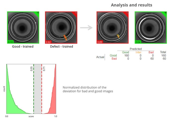
The image above showcases such an AI-equipped system. At the top left, we can see how the system is trained by providing it with images of both good products and defects.
The top right lists items analyzed by the AI-enabled machine: 160 items passed muster and were listed as good, while 60 were deemed bad. Notably, there is zero grey area, also called iter. Per the graph on the bottom left, the AI system identifies the good ones as those with a grade below 0.55, and the bad ones above 0.71. There are 0 iter, because AI’s enhanced ability to distinguish potential defects leads to very low false reject rates.
Specifically, the images at the top right are (left) 0.89, and rejected as it is higher than the 0.71 threshold; and (right) 0.04, and accepted as it is well below the 0.55 tolerance for good product.
Of course, little things matter — and AI is terrific at pinpointing the littlest of things. The product that registered an 0.04 — an easy pass — was nonetheless not deemed perfect. This item contains a few noticeable light reflections. However, these are not defects but rather inherent to this sort of inspection. Conventional vision systems alone may have identified this product as “bad,” running the risk of taking good, profitable product off the production line.
Since plungers can be quite cumbersome, a dual control system – such as the custom-designed one showcased below in Figure 1 — may be necessary to avoid high levels of false rejects. In Figure 1, the region of interest (outlined in green) is shown in a frontal view (right) and an angled top view (left). If an element is detected as an air bubble in one view but not the other, as shown in this figure, it does not need to be rejected. Critically, doubling up on optics allows the inspection station to discern non-reject-worthy anomalies from those necessitating rejection.
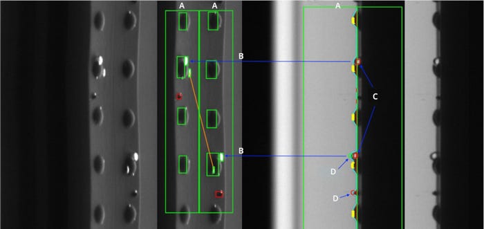
Figure 1. Top plunger inspection through two complementary views, a frontal view on the right and a top view on the left. A: Region of interest for particle detection. B: Air bubble in y-coordinate position, transfer from frontal to top view. C: Elements detected as air bubbles. D (top): Frontal view shows air bubble in same y-coordinate position. D (bottom): Frontal view shows no air bubble or plunger bump in this y position.
A dual-view optics setup is, in layman’s terms, a two-for-one. It allows for analysis of two spatially coherent views in one image. Such analysis would not be feasible in a system using two independent stations, as the information they generated would be impossible to correlate. Angled views tasked with inspecting plunger tops are combined with a frontal view monitoring the lateral. By combining two complementary views, inspection performance is improved and false rejects minimized.
Another inspection headache arises from the comparably small diameters of syringes — an issue that creates limited space in which particles can move and therefore be noticed. To inspect an injectable drug, the particles in the formulation might be made to move — a process that requires syringes to be rotated at speeds up to 9,000 revolutions per minute (rpm). Single rotation units on the carousel mandrels, such as those available on some machines, meet this need, and ensure flexibility in rotating a variety of drugs at speeds best suited to their individual inspection.
Different drug formula, different inspection formula.
Of course, so far as end users are concerned, syringes aren’t a finished product. It’s what they contain — vital injectable medicines — that make them valuable. And like the syringes themselves, the drugs they deliver also can pose significant challenges during inspection.
On the easier end of the spectrum are water-like liquids and light suspensions. Here, dynamic trajectory analysis increases detection probabilities since particles behave in a statistically measurable way. Toward the tougher end, drugs that present as heavier suspensions generally require more sophisticated strategies.
Let’s explore an anecdote: a vaccine presenting as a heavy suspension in a syringe could not be completely mixed up. While particles that stick to the syringe’s inner wall were reasonably easy to inspect, “noise” in the image related to the spin made it difficult to detect small particulates in the liquid portion. It was also difficult to differentiate clear particles (such as white fiber and glass).
As a solution, particle inspection was performed using continuous rotation. Each position in the carousel had an individual servo rotation unit with a specific rotation schedule. The position of some particles were correlated and found to be different relative to their location at the first station. From this position change, it was concluded that these were moving particles.
However, with gels or highly viscous products such as hyaluronic acid, inspection processes can’t rely on spinning to provide particle motion differentiation. In this case, the container is kept in rotation to cover the full 360-degree facade and track all visible potential contaminants, as portrayed in the red trajectories in Figure 2. The potential contaminants’ apparent speed is used to determine if they are inside or outside the container. They move on “different radiuses” at the same angular rate covering different displacements.
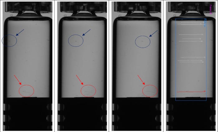
Figure 2. Objects in blue circles have been identified as external, while those circled in red are contaminants inside the container — in this case, fiber. In the right-most container, inside contaminants are signified by their red trajectory, with outside dirt given grey trajectories.
Here, proper lighting becomes paramount, as certain contaminants, such as white fibers, are more easily visible against a dark background. Many cosmetic defects, such as thin scratches, are easier to find against a dark backdrop as well.
Another potential snag can emerge. While the aforementioned high-speed rotation is generally sufficient for liquid short-molecule drugs, there may be instances where a container cannot be rotated at such velocity for product integrity reasons. For example, subjecting many biopharmaceutical drugs to such turbulence could impact their integrity. Also, with highly viscous drugs, particles generally don’t move and therefore cannot be distinguished via this common tactic.
In these situations, an apt solution may be three-dimensional inspection, which allows the inspection unit to infer whether a suspected contaminant is inside or outside the container by analyzing its trajectory. Specifically, the radius will be shorter if the foreign matter is inside, and longer if it is outside.
Finally, employing line-scan cameras can be another advantageous technique in syringe inspection settings. Especially effective for turbid liquids, line-scan cameras continuously capture images line by line, then stitch together a comprehensive image from as many as 10,000 exposures. By rotating the container at high speeds, the particles move toward the container barrel. Such setups are ideal for inspecting cylindrical surfaces, especially when it comes to cosmetic lateral side inspection.
Syringe inspection has always been a challenging facet of the post-production pharma quality control process, but with the right methods and machinery excellent results are nonetheless achievable. For both handling mechanisms and vision systems, it is a process that presents distinct hurdles to the mission-critical inspection of both devices and the formulations they deliver.
Given the various syringe and formulation types, seemingly the only constant with syringe inspection is variability. A best practices approach to syringe inspection means careful consideration of both the type of syringe and the drug it houses, as well as optimal utilization of lighting, rotation speed, and inspection technologies and methods.
About the Author(s)
You May Also Like

